
The Liquid-Cooled Solution.
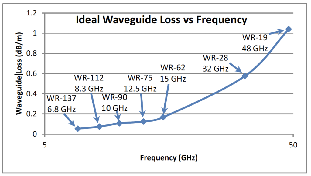
Many current teleport or gateway uplinks are implemented with outdoor TWTAs placed in hubs on the back of the antenna to keep the waveguide runs short. The resulting challenge of cooling the interior of the hub is significant, requiring large air conditioners that require frequent maintenance and are often are the least reliable component of the terminal.
New liquid cooling, as implemented in certain high power satcom uplink amplifiers, simplifies design and eliminates operational problems for hub-mount systems:
- No air conditioner in the hub – the number one maintenance and reliability problem
- No air flow requirements or ducting for HPAs in hub – simplifies layout, creates space,allows HPA placement closer to feed
- Eliminate most hub maintenance – no HPA fins or fan filters to clean or replace, no HPAfan failures, no air conditioner regular maintenance
- No HPA noise at the hub – remote the radiator or cooling element to a location with better environment and easier access and keep the neighbors (and the techs) happy
- No variation with temperature– closed loop flow control provides constant baseplatetemp even in extreme environments – reducing gain variation and extending life
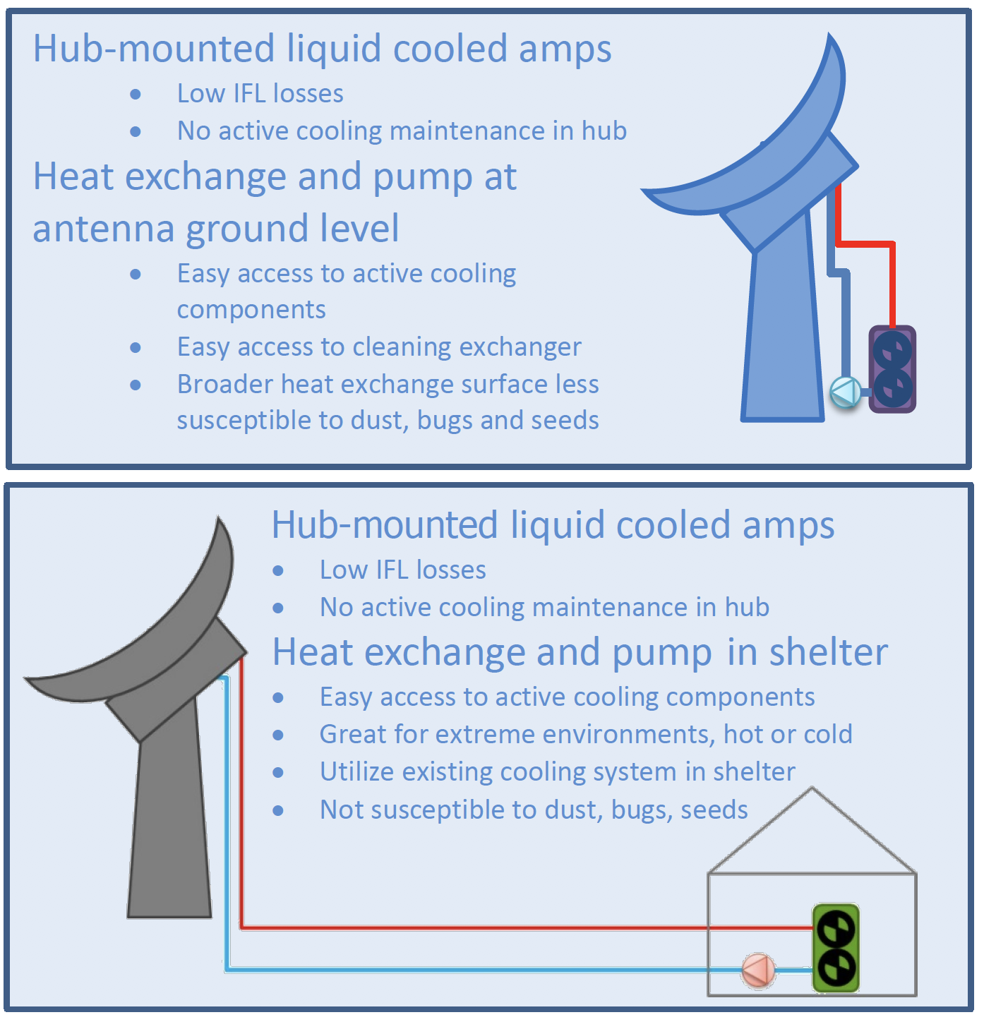
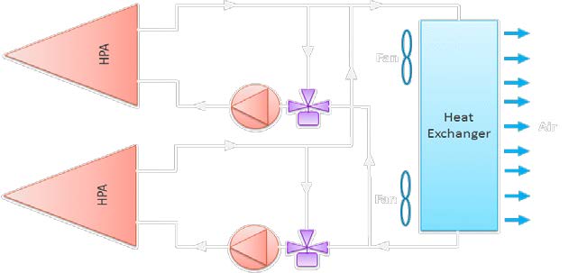
Figure 2. Options for liquid cooling outdoor hub-mounted HPAs
Other terminals use indoor HPAs such as Klystron amplifiers because they want to control the environment for the amplifiers to extend their life, or because they are near residential areas and cannot have the noise of the fans and air conditioning equipment running 24/7. These implementations spend a lot of energy and money on air conditioning the indoor environment, along with the building and rack space for this RF equipment, plus wasting power in long waveguide runs. Liquid-cooled HPAs can:
- Dramatically reduce thermal load on general air conditioning system – frees up airconditioning for other uses including expansion of baseband equipment
- Create the option to move HPAs outdoors even in urban or extreme environments withquiet, sealed units, no fins/fans to clean/maintain and no temp variation on HPAs
- Significantly reduce power consumption and thermal dissipation vs Klystrons with liquid-cooled indoor or outdoor TWTAs that draw much less power at lower output RF power
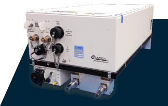
a)Xicom SuperCoolTM Liquid-cooled TWTA is the same as air-cooled in RF and power supply
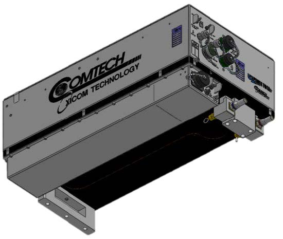
b)Baseplate and cooling are the only differences
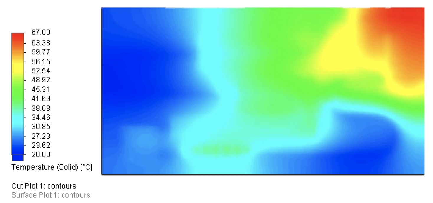
c) Thermal design of baseplate is custom for each amplifier to ensure margin
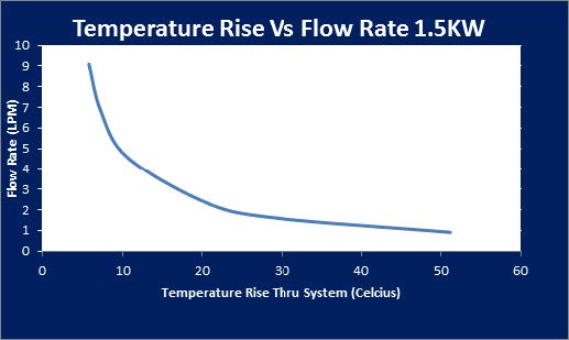
d)1.5 kW TWTA thermal design allows relatively low flow rates (5 l/min = 10⁰C rise)
e) Dripless connectors prevent leaks and messes
Cooling System Design
The HPA is only one part of the cooling system; the rest can vary widely depending on the installation location, available resources, and constraints. Many larger facilities have chilled water on site for air conditioning, and a small portion of the chiller’s capacity can be used to cool the HPAs. Other terminals will require a dedicated liquid-to-air cooling system. These dedicated systems can be implemented as either above ambient heat exchangers (Fig 4a) or as temperature controlled chillers (Fig 4b). The heat exchangers have no refrigeration cycle and are therefore simpler, more economical, and easily controlled. Most applications for the new liquid-cooled HPAs can easily work with a simple heat exchanger. However, they have a limited cooling capacity, especially in cases where the ambient air temperature is relatively high. For these cases, a refrigerated chiller may be selected to allow for maintenance of the baseplate temperature much closer to the ambient air temperature. These systems are more complicated, cost more, and may require more maintenance. However, they can still be quite compact and can support a wider temperature range of operation.
a) Above-ambient liquid-to-air heat exchanger
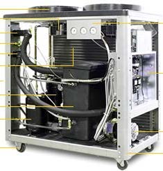
b) Refrigerated liquid-to-air chiller
Cooling systems can be controlled passively with a thermostat which measures the liquid temperature and adjusts flow through the heat exchanger to maintain the desired temperature of the coolant (Fig 5). This simple and economical approach using all passive components is similar to automotive engine cooling systems. The primary alternative, active control valve modulation (Fig 6), uses a controller and more precise temperature feedback available from the critical portion of the HPA to control the valve that adjusts how much of the liquid passes through the heat exchanger. Active control requires some additional engineering but provides better temperature control of the TWTAs RF components.
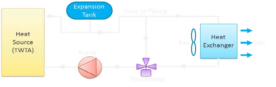
Figure 5. Passive control liquid cooling systems are simple and economical
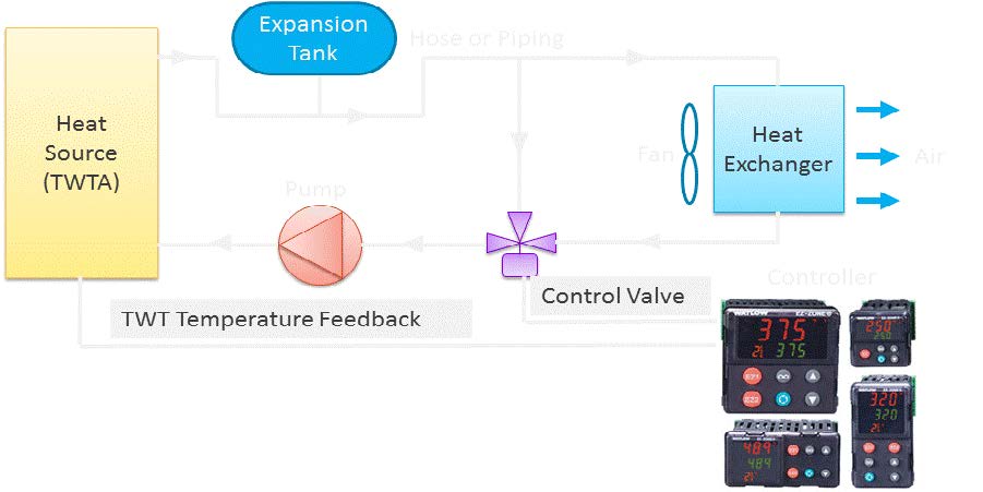
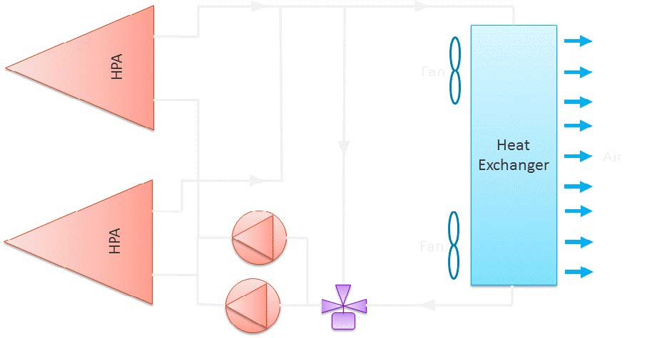
Figure 6. Active control valve modulation liquid cooling systems are higher performing
There are many redundancy options for liquid cooling systems, and each system designer must consider their availability and maintainability requirements along with operational considerations when choosing one. The basic 1-for-1 redundant system (Fig 7a) provides a separate cooling system for each of two redundant HPAs. This requires no complex design, but does not lower cost through shared elements or improve system reliability through shared redundant systems. To share one of the larger elements in the system, a single heat exchanger can be used for both HPAs while maintaining dedicated pumps and thermostats (Fig 7b). This can reduce the system’s space and cost without impacting reliability. Further consolidation and improved redundancy can be accomplished by tying redundant pumps together with a single heat exchanger and thermostat (Fig 7c) so that either pump could support operation of either HPA. Thus, some additional plumbing improves availability.
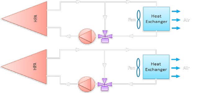
a. One-for-one redundant cooling systems
b. Single heat exchanger with dedicated pumps and thermostats
c. Single heat exchanger and thermostat with redundant pumps
Cooling System Equipment
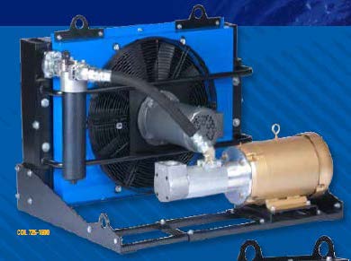
The key types of equipment in the above-ambient heat exchanger type cooling systems are widely available and not expensive. There is a lot of flexibility in the available equipment to adapt to the requirements of any implementation such as high pressure needed for pumps installed a long distance from or well below the operational HPAs. The heat exchangers specifically can be indoor or outdoor rated for placement near the hub either in a shelter or out of doors, and are available in sizes rated to thermally dissipate from 1 to over 10 kW. Heat exchangers can be purchased in combinations including integrated fans or even integrated pumps as well (Fig 8a and b). The exchangers come in standard sizes, and must be selected for the thermal load (HPA), but the manufacturers provide easy to read charts to support this (Fig 8c). HPAs are at the low end of standard thermal loads for these; a typical TWTA could be cooled with a standard combined exchanger size of 13” X 16” X 27”.
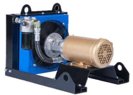
a) Combined heat exchanger, pump and fan
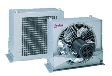
b) Heat exchanger with built-in fan
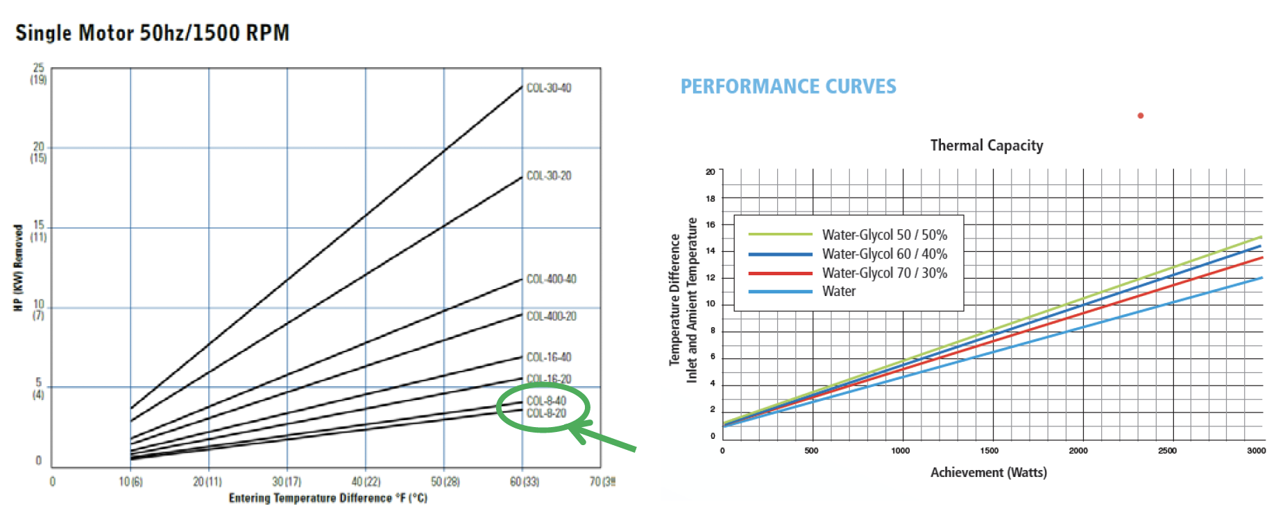
c) Manufacturer’s charts for sizing heat exchanger for thermal load
Pumps for cooling systems have improved significantly and are built for reliability. Available pumps have magnetic drive to eliminate bearings as a failure item and have no shaft seals to increase MTBFs. There are pumps with high flow rates available for applications with multiple HPAs, and there are pumps with high head pressure to support long distances between the heat exchanger and the HPA and also heat exchanger locations well below HPAs (Fig 9).
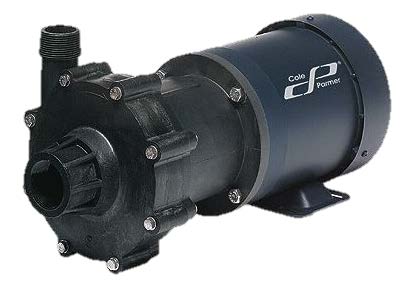
a) Magnetic drive high flow rate pump
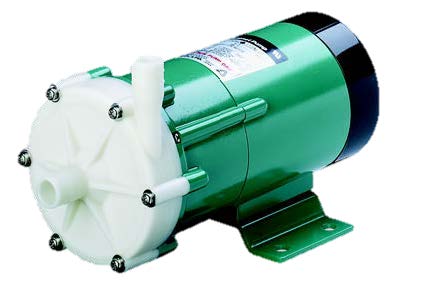
b) Magnetic drive high head pressure pump
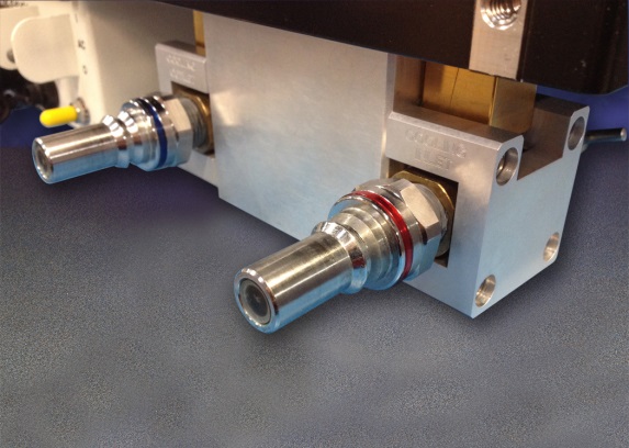
Drip-free connectors are one of the most exciting advances in these cooling systems (Fig 10). These connectors have been designed to allow easy, no-tool connect/disconnect for quick HPA changeout, and are dripfree even when disconnected under pressure. This eliminates spillage during installation and service without any extra time for the technician. They are available with hose barb or NPT thread interfaces for use with hoses and pipes, and there are even rotating joints available for connection to rotating assemblies such as full motion antennas.
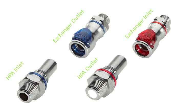
Figure 10. Drip-free connectors make connections fast, clean and reliable
Finally, connections between cooling system elements are typically a combination of piping and hoses to adapt to the implementation. There’s a large range of flexible hoses from the hydraulics industry that handle a wide temperature range and include UV rated offerings for outdoor installations. Rigid piping is typically used for longer distances and support. Metal piping provides greater support at greater cost while plastic piping costs less and is easier to work with – but provides less support. Depending on site requirements, rigid piping can be buried or above ground, and can run long distances – 10’s or 100’s of meters – for which you can use insulated piping to reduce impact on heat exchanger thermal load.
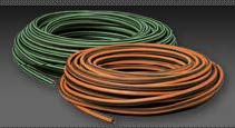
Figure 11. A wide range of pipes and hoses are available for installation flexibili